Wireless RGB LED Controller Using 433MHz RF Modules and Arduino
Projects that involve wireless data transmission are always a lot of fun – as well as projects that invole RGB LEDs. So today we will combine the two and build a wireless RGB LED controller using two Arduino Nanos and one of these cheap 433MHz RF transmitter and receiver kits.
The project consists of two parts: The transmitter circuit and the receiver circuit. On the transmitter side there are 3 potentiometers that can be used to set the red, green and blue values for the RGB LED. The Arduino then constantly reads the analog values from the potentiometers and sends them to the receiver. The receiver side Arduino will then receive the RGB values and output them as analog voltages to the RGB LED.
Parts
- 2x Arduino Nano (Uno works as well of course)
- 1x 433MHz RF transmitter and receiver kit
- 3x 1kΩ Potentiometer (10kΩ should work as well)
- 1x RGB LED (I use one with a common anode but common cathode works too)
- 3x 1kΩ Resistor
- 2x Breadboard
- Jumper wires
The RF Modules
For the wireless data transmission I will use a 433MHz wireless transmitter and receiver kit from AliExpress (like this one; no advertisement):
The transmitter doesn’t feature any complex signal modulation but only transmits the signal by completely turning on or off the carrier wave. This technology is called “Amplitude Shift Keying”, since the data signal influences the amplitude of the 433MHz carrier wave:
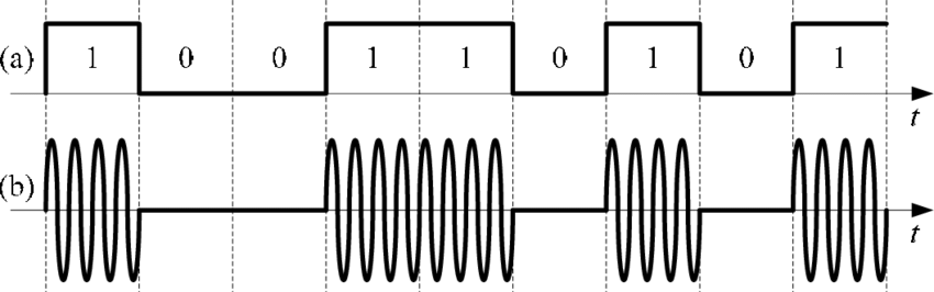
(a): Data signal, (b): Output signal (Image Source)
When a ‘1’ is transmitted, the carrier signal turns on and when a ‘0’ is transmitted the carrier signal turns off. This is not the most reliable type of signal modulation but it’s reliable enough for our project when combined with a powerful encoding library, that makes sure that the data is transmitted and received correctly.
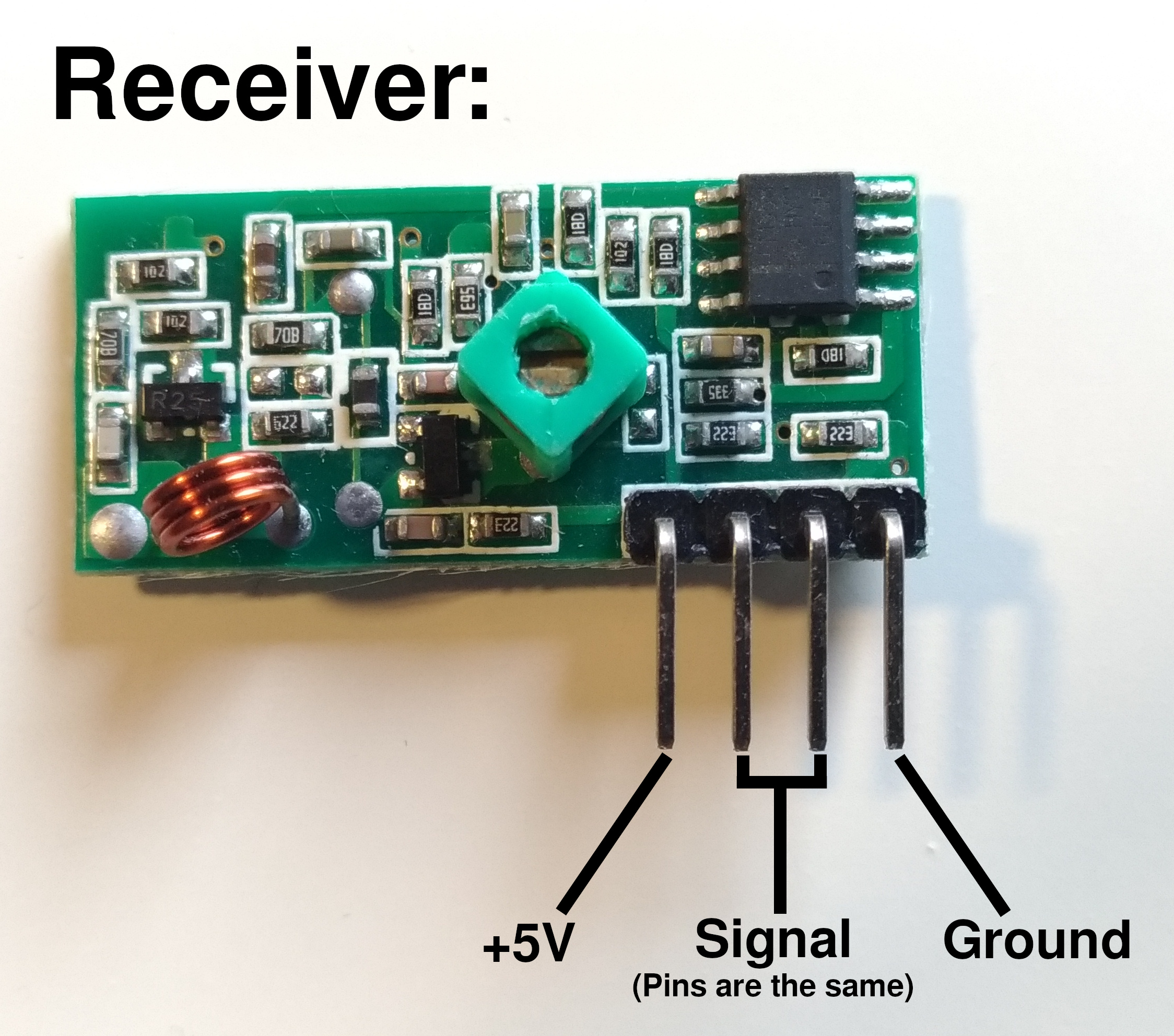
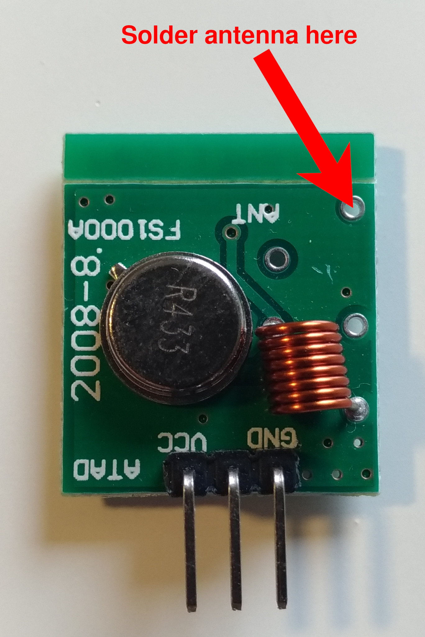
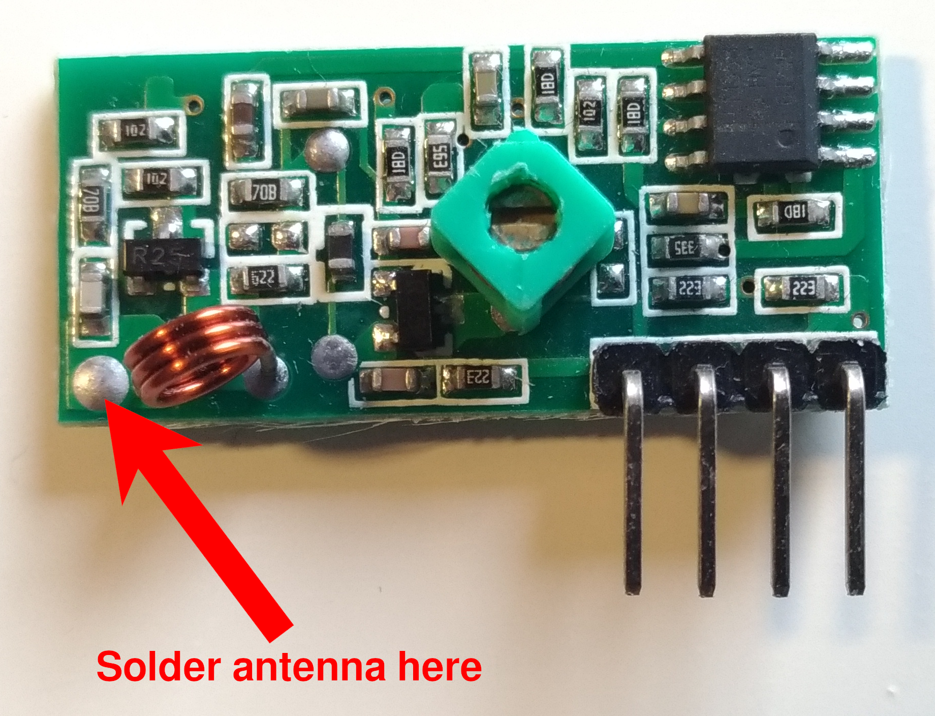
The pinout of the modules is as shown in the pictures:
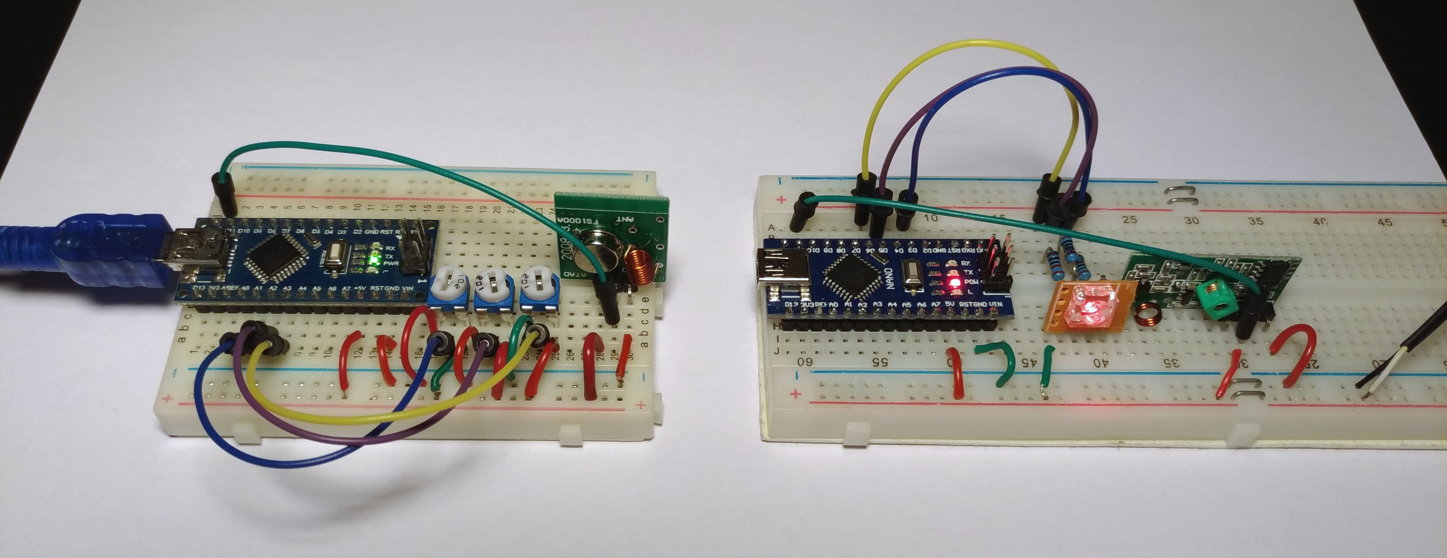
The Wiring
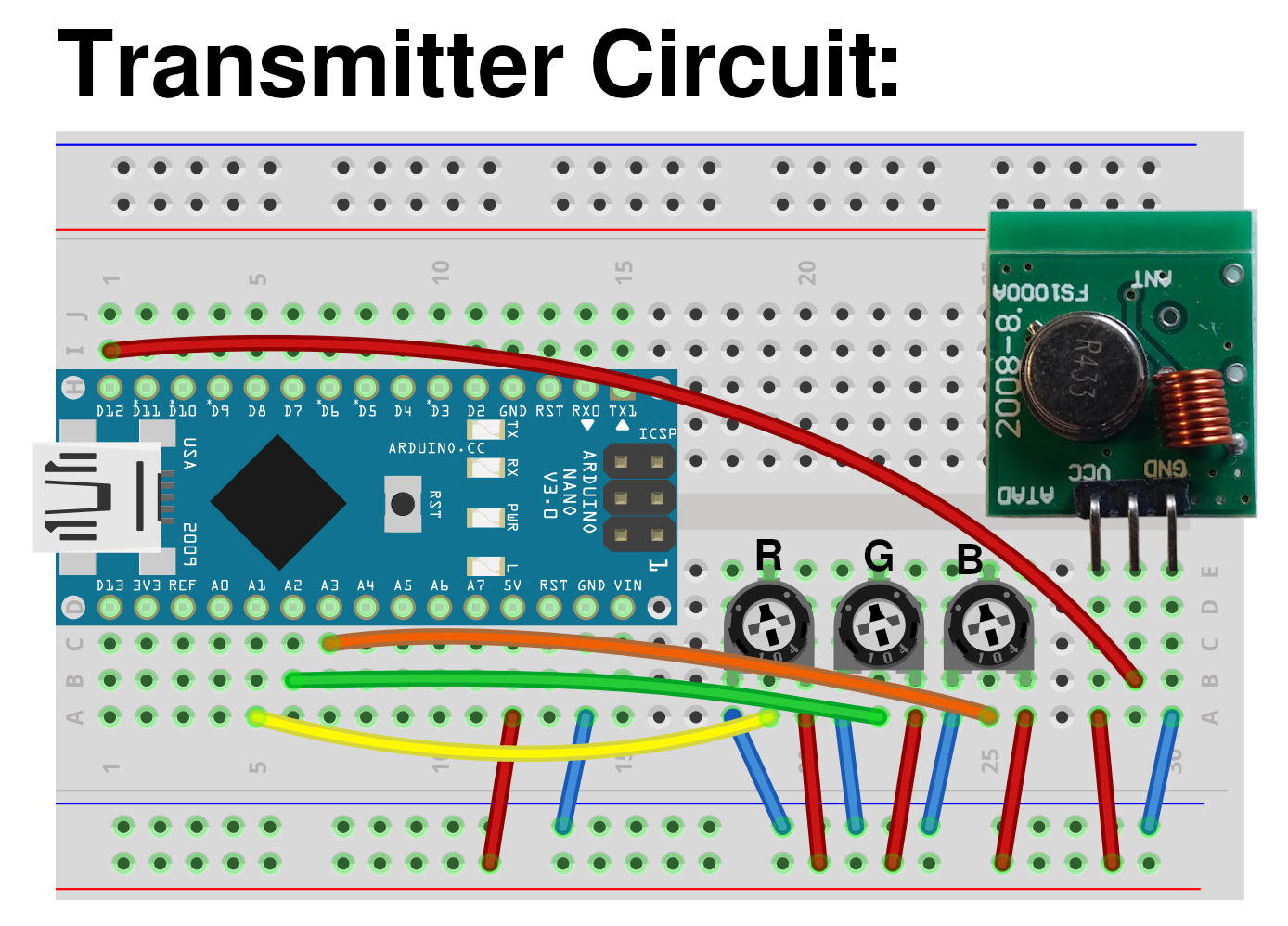
Transmitter:
Pin 12 –> RF Transmitter Signal Input
Pin A1 –> Potentiometer Red
Pin A2 –> Potentiometer Green
Pin A3 –> Potentiometer Blue
Receiver:
Pin 11 –> RF Receiver Signal Output
Pin 3 –> RGB-LED Red Channel
Pin 5 –> RGB-LED Green Channel
Pin 6 –> RGB-LED Blue Channel
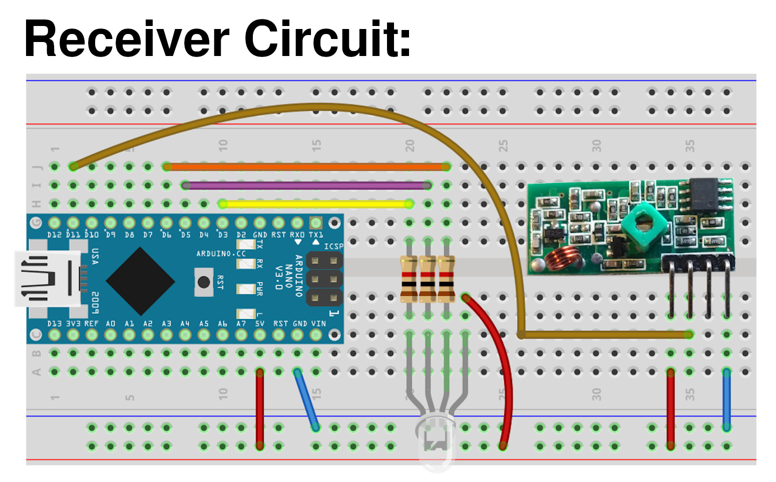
Note: Since I use a common anode RGB LED, the common pin must be connected to +5V and the IO-pins act as the ground pins for each color. If you use a common cathode LED, connect the common pin to Ground instead.
The code
Since we have one transmitter and one receiver, we obviously need to create two different Arduino sketches. One for the transmitter’s Arduino Nano and one for the receiver’s.
For the wireless communication we use the RadioHead library. This library entirely handles all the sending and receiving of the data and makes sure that corrupted data is not accepted by the receiver.
Just download the library’s ZIP file from GitHub and import it in the Arduino IDE via Sketch -> Include Library -> Add .ZIP Library…
RadioHead supports several transmission techniques but since our RF modules only support Amplitudy Shift Keying (ASK), we only include the RH_ASK.h library and not all RadioHead libraries that are provided by the ZIP file.
Because RadioHead requires Arduino’s SPI library to function, we include it as well.
Transmitter Code
// transmitter.ino

// include libraries:
#include <RH_ASK.h>
#include <SPI.h>

// Create an instance of the RadioHead ASK handler:
// -> Default pins for the RF modules:
//    Pin 11: Data input from receiver
//    Pin 12: Data output to transmitter
RH_ASK radio;

// Create and initialize three 8-bit variables for our RGB values:
uint8_t r = 0;
uint8_t g = 0;
uint8_t b = 0;

void setup() {
  // initialize the RadioHead library:
  radio.init();
}

void loop() {
  // constantly read in the analog values from the potentiometers:
  if(readValuesCheckHasChanged()){
    // if the values have changed (-> function returns true), send the values to the receiving device:
    sendValues();
  }
}

bool readValuesCheckHasChanged(){
  // read the analog values from the potentiometers and save them into local variables.
  // -> analogRead() provides 10-bit values (0 - 1023) but we only need 8-bit values (0-255), so divide the values by 4:
  uint8_t rr = analogRead(A1)/4;
  uint8_t gg = analogRead(A2)/4;
  uint8_t bb = analogRead(A3)/4;

  // check if any of the read values differs from the previous values:
  if(r != rr || g != gg || b != bb){
    // if yes, assign the latest RGB values to the global color variables and return true:
    r = rr;
    g = gg;
    b = bb;
    return true;
  }
  // if nothing has changed, return false:
  return false;
}

void sendValues(){
  // put the individual 8-bit RGB values into an array:
  uint8_t dataArray[] = {r, g, b};
  // RadioHead requires the pointer to the array as a parameter, so let's obtain the pointer first:
  const uint8_t *data = dataArray;

  // push the pointer to the data as well as the length of the data (= 3 Bytes) to the RadioHead instance:
  radio.send((uint8_t *)data, 3);
  // wait until RadioHead has sent the entire data packet to the receiver:
  radio.waitPacketSent();
}
Receiver Code
// include libraries:
#include <RH_ASK.h>
#include <SPI.h>

// Create an instance of the RadioHead ASK handler:
// -> Default pins for the RF modules:
//    Pin 11: Data input from receiver
//    Pin 12: Data output to transmitter
RH_ASK radio;

// Create and initialize three 8-bit variables for our received RGB values:
uint8_t r = 0;
uint8_t g = 0;
uint8_t b = 0;

void setup() {
  // initialize the RadioHead library:
  radio.init();

  //declare pin 3, 5 and 6 as output pins so that the analog voltages for the RGB LED can later be written to them:
  pinMode(3, OUTPUT);
  pinMode(5, OUTPUT);
  pinMode(6, OUTPUT);
}

void loop() {
  // create an empty array of 8-bit variables that is used to store the received data:
  uint8_t data[3];
  // store the expected data length in a variable (3 Bytes: One for r, g, and b):
  uint8_t dataLength = 3;

  // check if data has been received by RadioHead and push the empty array as well as the
  // expected dataLength to RadioHead, so that it can store the received data inside the provided array:
  if(radio.recv(data, &dataLength)){
    // when data has been received, extract the received RGB values from the array:
    // -> The order must be the same as in the dataArray[] on the transmitter side (here: 0: red, 1: green, 2: blue):
    r = data[0];
    g = data[1];
    b = data[2];

    // afterwards write the received values to the analog pins of the RGB LED:
    outputValues();
  }
}

void outputValues(){
  // write the RGB values stored in the global r, g and b variables to pin 3, 5 and 6 where the RGB LED is connected:
  // -> Since I used a common anode RGB leds, the analog pins act as the ground pins of the LED. Therefore the signals must be inverted,
  // e.g. '0' means full brightness and '255' means completely dark.
  analogWrite(3, 255-r);
  analogWrite(5, 255-g);
  analogWrite(6, 255-b);
}
The Result
After you have built the circuits and uploaded both Arduino sketches, you’re ready to go. Connect the Arduinos to different power sources. If possible, use a power bank as the power source for the transmitter circuit so that you can walk away from the receiver and test the range.
Now use a screw driver to turn the potentiometers on the transmitter side. If everything works, you should see the color of the RGB LED changing accordingly to the potentiometers.
To see the circuit in action, watch the video at the top of the page.
Increasing the Range (Optional)
When you use the RF modules without any modifications, the transmission will only work over a distance of less than a meter. Of course this distance is not sufficient for most applications, but fortunately there is a cheap and easy way to increase the range to up to 10m:
The solution is to attach an antenna to the transmitter as well as the receiver. The length of the antenna should be about a quarter of the wavelength. Since the according wavelength of 433MHz is 69cm, your antenna should be about 17cm (7 inches) long.
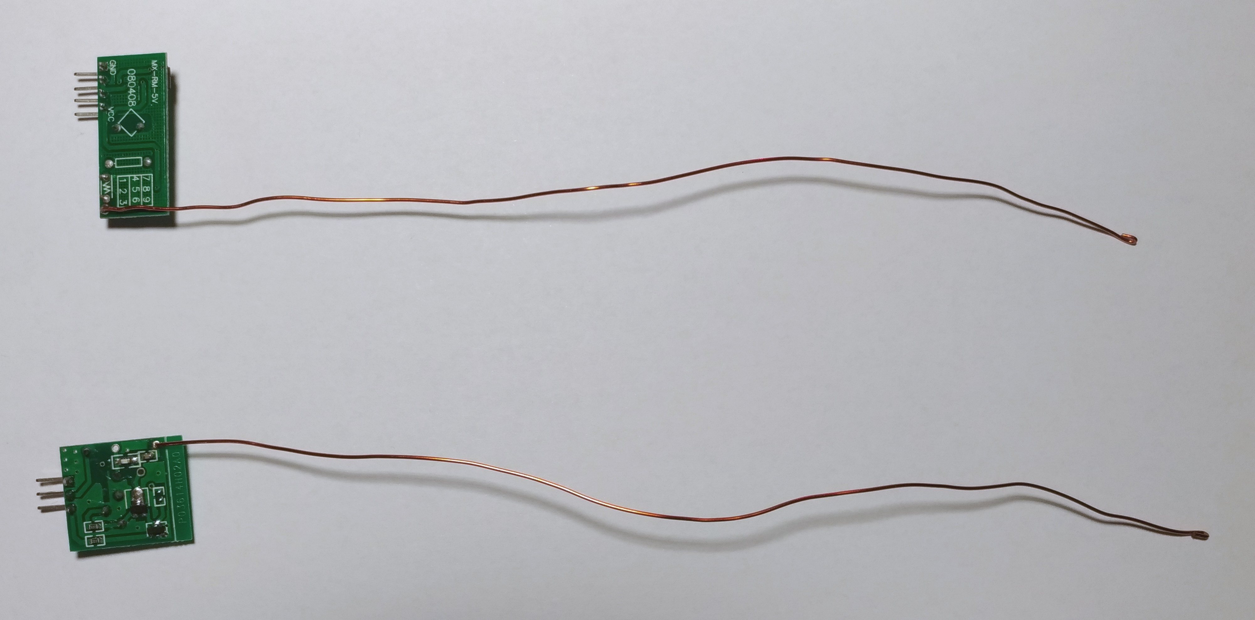
The antenna can be any piece of wire that you have laying around. I used some enameled copper wire that I salvaged from an old washing machine motor.
Attach the antennas to the modules as shown in the pictures:
The modules with attached antennas then look like this:
Troubleshooting
With some power supplies the RF modules don’t work properly because they interfere with electrical noise from the power supply. In most cases you can fix this by simply connecting a high value capacitor (>=100μF) between +5V and Ground. The capacitor smoothens the supply voltage and therefore reduces noise. If you can’t get it to work that way, try a different power supply.
Additionally, you might have noticed the little tuning potentiometer on the receiver module. This is a variable inductor that determines the receiving frequency. By turning it with a screw driver you can slightly modify the receiving frequency so that it matches the carrier frequency of the transmitter module. Just try multiple settings until you find one that works.